Understanding AutoFittingOptions.xml
Automatic routing behavior is controlled by a project level settings file named AutoFittingOptions.xml. This file can be modified with a text editor to customize auto-fitting behavior.
Navigate to the data folder inside the active project to find AutoFittingOptions.xml.
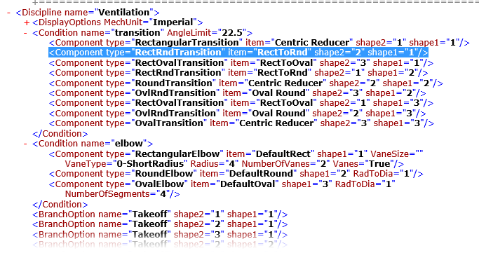
The contents of AutoFittingOptions.xml are arranged into two main disciplines. Ventilation (HVAC) and plumbing disciplines are subsequently divided into conditions. It is at the conditions level of this hierarchy where the shape and type arguments determine auto placement behavior.
Each condition argument begins with shape values for the end condition of the segments to be connected, followed by type and item values. Shapes are classified with the integers 1, 2 and 3 indicating rectangular, round and oval shapes respectively. Depending upon which combination of shape values are presented, the values for type and item are defined by the DataGroup catalog type's display name and the component item name as seen in the application placement tools.
<Component type="RectRndTransition" item="RectToRnd" shape2="2" shape1="1"/>
The example above indicates a route where a rectangular shape transitions into a round shape. The fitting which connects the two differently shaped segments is the RectToRnd transition.
If the first and second route segments are not in line, the arguments in the condition named elbow apply. If the shape and or size differ between the first and second route segments, then both the transition and elbow condition arguments are solved. This results in a route which has a combination of an elbow and a transition between the route segments.